
WHAT IS AN ATS CONTROL PANEL
An ATS (Automatic Transfer Switch) controller is the ideal choice in cases where you have to control a power generator that is connected to the Mains in a standby configuration. This system is always waiting fora failure of the power utility. An ATS control panel automatically manages the connection assignment of the LOAD to MAINS or GENERATOR. The panel includes an automatic battery charger and a set of electronic circuit boards complete with power relays that interface with the engine Auto Start module. The ATS controller is conveniently tasked with driving the contactors. Despite the fact that the power configuration is the same for all panels, the dimensions and weight depends on the nominal power of the ATS control panel.
ATS CONTROL PANEL PRICE LIST 2016 WHAT IS AN ATS CONTROLLER
THE CORE OF AN ATS CONTROL PANEL
Out of any doubt the core of a good ATS panel is the ATS controller. Bernini Design manufactures state-of-art ATS controllers micro controller based. Despite the complex software the product in your hands is user friendly and in any case let you full manual control of the system. Thanks to solid state display and indicators you can benefit of an high reliability in a full operating range -30°C up to +70°C. Be28 ATS controller is the best choice.YOU MAYBE INTERESTED IN REMOTE GENERATOR MONITORING
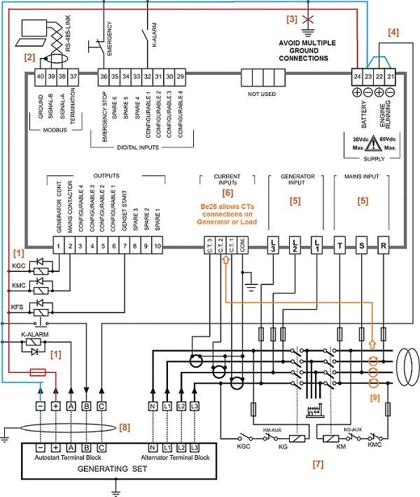
TYPICAL ATS CONTROL PANEL WIRING DIAGRAM USING CONTACTORS
HOW TO USE AN ATS CONTROL PANEL
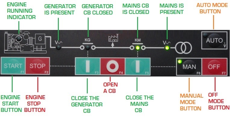
The ATS CONTROLLER BE28 features a simple and user friendly interface. Each command is committed to make a specific and intuitive function. The front fascia features high-brightness indicators to make you understand immediately the status of your electric system.READ MORE ABOUT THE ATS CONTROLLER DESCRIPTION
WEB SEMINAR ABOUT AUTOMATIC TRANSFER SWITCH CONTROLLER
HOW THE AUTO MODE OF AN ATS CONTROL PANEL WORKS
The
AUTO mode is the most interesting ATS control panel mode of operation.
The main ATS controller duty is to continuously monitor the status of
the MAINS. The ATS controller allows you to set low/high limits for
Mains Voltage and Frequency. You can program limits for the difference
of voltage between phases. You can set a preferential phase rotation as
well (CW or CCW). Additionally, you can set a limit of power. In other
words you can disconnect the load from the MAINS when the request of
energy rises above a certain limit. All these parameters are compared
with the status of the Mains. When the ATS control panel will find an
abnormal situation (for a defined period of time), the ATS control panel
will disconnect the load from the Mains. This helps you preventing a
severe damage to your load. You can imagine what will happen supplying a
power equipment rated at 380-440Vac with a supply of 200V! Or worse
than that, if by mistake someone changed the rotation of the phases (by
connecting the wires in a different order) and you have to supply a
3-phase electric motor. Not mention the problems caused by over
voltages. We can say that the ATS plays an important role; more that a
simple Automatic Transfer Switch. Then, if the failure persists for over
the programmed time, the ATS control panel will send a command to start
to the generator Auto Start Module fitted on the diesel
generator. After starting the generator, the ATS control panel will
check the quality of the generator electrical parameters (again here you
can set limits on several parameters). Once detected that the
parameters are within the allowed limits, the ATS control panel will
close the generator circuit breaker. In case of prolonged power outages,
your load is safely supplied by your emergency generator and the ATS
control panel continuously monitor the system. You can set limits of
load or current in order to prevent overloading
of your generator. The ATS control panel as mentioned above does not forget to monitor the Mains! So, when the Mains parameters will return within the programmed settings, the ATS control panel will transfer the load to MAINS. This will happen after a delay that will ensure that the Mains is in stable conditions. Once your load is connected to the Mains, the engine will run for a programmable time (so called COOLING DOWN TIME) without load. After the cooling down time the engine will stop and the ATS control panel is ready for a new power outage. The ATS control panel features a MANUAL mode and a TEST mode of operations. This adds flexibility to your system and you can take the control of the load under your
fingers.
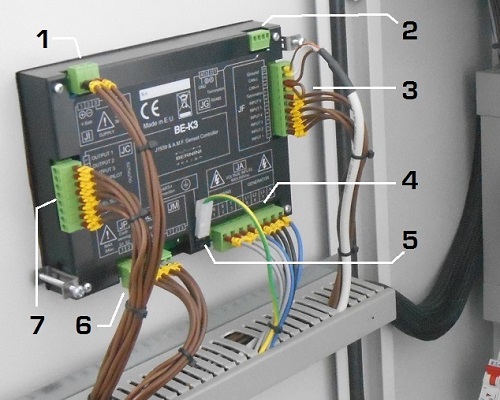
ATS CONTROL PANEL CONNECTIONS
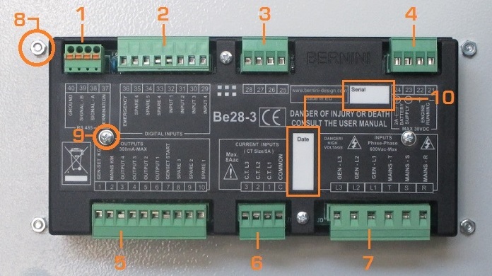
[1] RS485 SERIAL INTERFACE [2] CONFIGURABLE DIGITAL INPUTS[3] CONFIGURABLE SPARE INPUTS [4] POWER SUPPLY
[5] CONFIGURABLE STATIC OUTPUT CONNECTIONS
[6] 3-PHASE CURRENT TRANSFORMER CONNECTIONS
[7] ALTERNATOR & MAINS VOLTAGE CONNECTIONS
[8] REAR COVER FIXING SCREWS [9] FIXING SCREWS
[10] RESERVED AREA FOR END USER INFORMATION
THE WIRING DIAGRAM OF AN ATS CONTROL PANEL
Ancillary devices are normally provided, example: RS485 serial interface, remote control, monitoring systems, Modems, Internet connection and so on. Available sizes on the market are normally in the range 10-1000kVA. This is the basic Panel Circuit Diagram configuration with an ATS controller. The ATS controller is wired to the MAINS via protection fuses. The fuses protects the cables from short circuits. The ATS Controller presents normally an high impedance over 4 Mega ohm on the voltage measurements inputs. The ATS controller is wired to the GENERATOR via protection fuses in the same way as above.Current of the generator is measured via Current Transformers. The ATS controller drives the coils of the Switch-gears. The ATS controller is connected to the engine via cables. In some cases extra driver relays are required if the distance is over 100 meters. The ATS controller provides a request of start (R.O.S) to the local Auto Start module controller. The ATS controller is optionally tasked to monitor and charge the battery via a battery charger. The supply of it is protected by fuses. The Power Circuit Breakers are included in the panel in a way to connect the Load to the Generator or Mains.A serial interface allows you a remote control and monitoring. The components are inclosed in a steel cabinet. The frontal doors features a key lock to avoid NOT-authorized access and an Emergency Switch to disable the panel and/or the Generator. A more complex ATS panel may include extra relay for extra-alarm indication and electronic boards to interface with external programmable logic controller. All modes of operation are normally chosen directly on the front panel of the Automatic Transfer Switch Controller, but in some cases some extra key-switches are required to switch the mode of operation. All connections to the panel are made via terminal block with a proper size. The most advanced ATS control systems provides a Canbus module to interface with SAE J1939 compatible engines. In this way the ATS control panel send the start request directly to the ECU's engine.
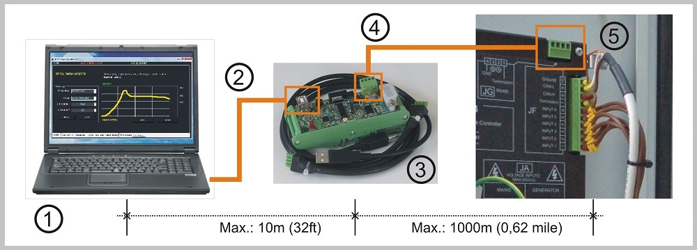
ATS control panel MODBUS monitoring
Using the USB driver you can control the ATS control panel from a remote location.
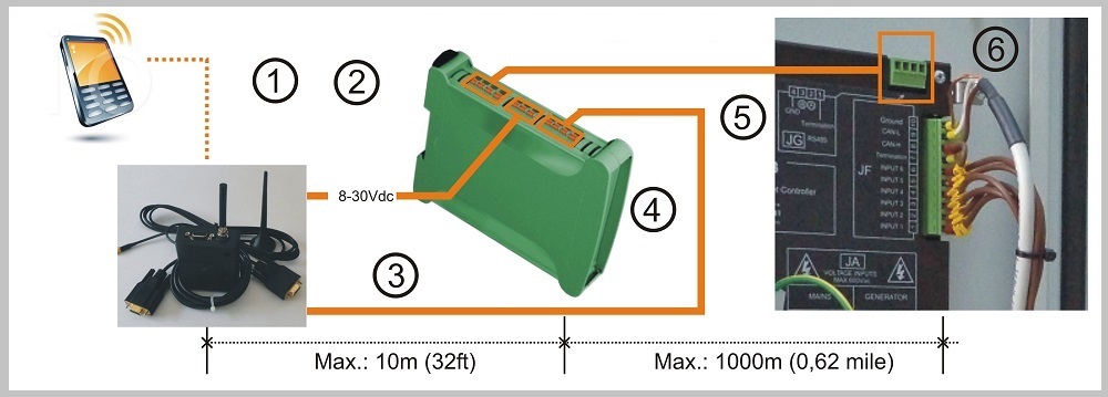
ATS control panel GSM monitoring
Using Be16 you can control and monitor the ATS control panel using a GSM mobile phone.
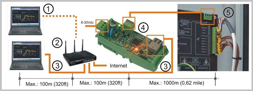
ATS control panel Internet Monitoring
Using the TCP-IP SERVER you can control and monitor the ATS control panel using via Internet.
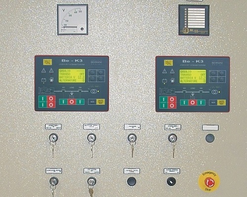
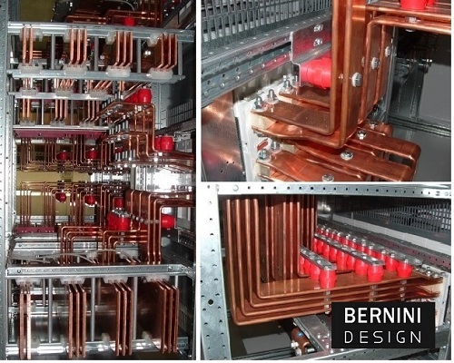
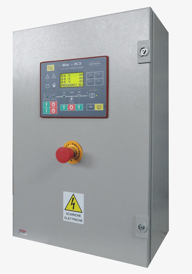
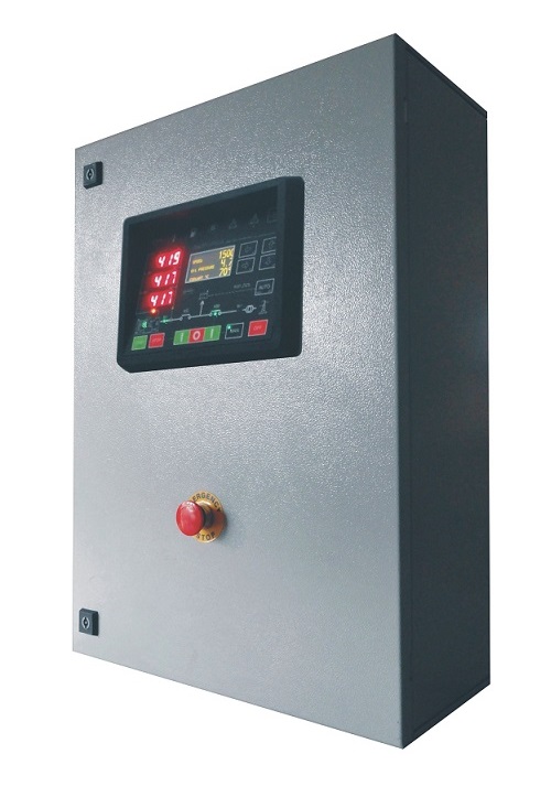
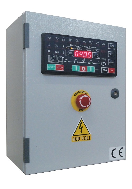
ATS CONTROL PANEL GALLERY


خارج الموضوع تحويل الاكوادإخفاء الابتساماتإخفاء